Typical PM Insulation Layout
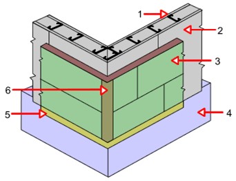
- Structural Frame
- Sheathing
- Extruded Polystyrene XPS
- Foundation
- Casing Bead with Starter Strip
- Welded Wire Corner Aide or Corner Bead
NOTES:
- 2 lb/ft density expanded polystyrene (EPS) in compliance with ASTM C578-87a also suitable.
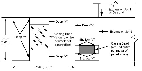
- Shallow “V” Surface Mount Control Joint used within 150 ft panels for stress relief.
- Deep “V” Expansion Joint used to divide walls into panels of maximum 150 ft and at floor lines with limited movement (less than 1/4″ [6mm]). Length to width ratio of panels defined by joints not to exceed 2:1.
- Expansion Joint used at joints in existing construction, dissimilar materials or construction, floor lines, changes in building height, and other locations of anticipated building movement.
- Casing bead used around perimeter of windows, doors, and other penetrations through the system
Typical PM Insulation Layout
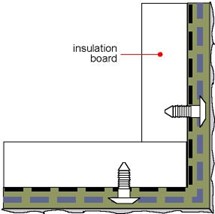
Corner Details – PM
 Outside Corner with Corner Bead (applied beneath mesh) |
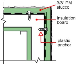 Outside Corner with Corner Aid (applied over mesh, minimum 1/8″ [3mm] base coat required over Corner Aid) |
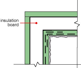 Inside Corner with Mesh Overlap (minimum 3″ [75mm] overlap in each direction) |
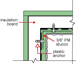 Inside Corner with Corner Aid (applied over mesh, minimum 1/8″ [3mm] base coat required over Corner Aid) |
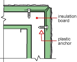
NOTE: Plastic anchors should be inserted at 16″ on center.
Enlarged Corner Section – PM
Control & Expansion Joint Locations
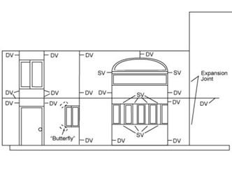
JOINT KEY
DV – DEEP V CONTROL JOINT
Uses:
- To divide wall areas into panels 150 square foot maximum area with maximum dimension 18 feet.
- Floor lines and dissimilar substrates
- At masonry wall joints. If adjacent masonry wall segments are on a common foundation and maximum movement is 1/4″
SV – SHALLOW V SURFACE MOUNT CONTROL JOINT
Uses:
- Inside 144 square foot panels for:
- Stress relief at window and door corners
- Color separations
- Aesthetic Effects
EXPANSION JOINT
Uses:
- At isolation joint in the substrate
- At new construction joined to existing construction
- All locations of movement greater than 1/4″
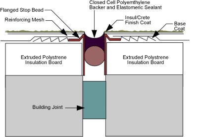
DV: Deep V Control Joint Section – PM
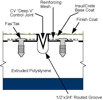
Reinforcing mesh may be placed under flanges on zinc control joint beads.
SV: Shallow V Control Joint Section – PM
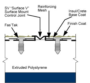
Note: SV “Surface V” Control Joints do not provide the same stress relief capabilities as DV Joints. For limitations of use, please see the Joint Key.
Expansion Joint Section – PM